Commercial Underfloor Heating Control with Modbus and BMS Integration
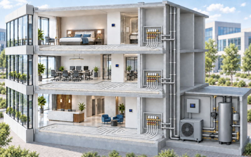
Keeping room-level hydronic zoning local while giving the building-management system the visibility it actually needs
Hydronic underfloor heating is often associated with residential projects, but the control problem changes when the same technology is used across offices, reception areas, clinics, education spaces or other commercial zones. The floor loops still need stable room-by-room control, while the facility team may also expect schedules, operating status and supervisory access through the building-management system.
The useful solution is not to make the BMS directly operate every thermal actuator. In this application, room thermostats and the wiring center continue to handle the local heating sequence. Modbus provides the supervisory layer, allowing the wider building controls to coordinate with the zones without replacing the control logic that belongs close to the rooms and manifold.
Building Type | Commercial building with multiple occupied heating zones |
Heating System | Hydronic underfloor heating |
Local Room Control | Individual room thermostats |
Zone Output | Thermal actuators on manifold circuits |
Central Coordination | Wiring center / zone control |
Building Integration | Modbus communication to DDC/BMS |
Optional Inputs | Floor or remote temperature sensor where required by the application |
Project Objective | Maintain dependable local UFH zoning while adding centralized monitoring and operating coordination |
In a home, a thermostat, actuator and manifold may be enough to meet the control requirement. A commercial building introduces another layer. Different areas can follow different occupancy patterns, facilities staff may need a consistent overview of room conditions, and heating operation may need to sit within a wider building schedule.
At the same time, underfloor heating remains a slow-response thermal system. Its control should not be treated like a fast fan-coil system. Repeated aggressive setpoint changes from a supervisory system can work against the thermal behavior of the floor rather than improve it.
The project therefore needs a clear division of responsibility: local controls regulate the heating zones; the BMS supervises, schedules or adjusts agreed parameters at a higher level.
· Each occupied area needs its own temperature control rather than one setpoint for an entire floor.
· Multiple manifold loops may belong to one room and need to respond to the same zone demand.
· The boiler or heat pump should receive a meaningful heating demand when one or more zones require heat.
· The facility team needs centralized visibility without turning every actuator into a separate BMS control point.
· Communication loss should not make basic room heating dependent on the supervisory network.
· Commissioning must remain repeatable across many zones, especially where several manifolds are installed.
These requirements make the architecture more important than the thermostat feature list. The project works best when local zoning is complete in its own right and BMS integration is added above it, rather than using the BMS to reconstruct basic room control.
Each controlled area uses a room thermostat to measure temperature and determine local heating demand. The thermostat is associated with one or more thermal actuators serving the relevant manifold loops. A larger room with several loops can therefore remain one comfort zone instead of being split simply because the manifold has several outlets.
The wiring center organizes the actuator outputs and, where the system design provides for it, combines active zone demand into a heat-source request. This keeps the plant-side control relationship clear: room demand opens the required circuits, while the boiler or heat pump is requested only when the heating system actually has a zone calling for heat.
Floor or remote sensors can be included where the application needs floor-temperature protection, a different sensing position or another project-specific control condition. Their role should be defined during design rather than added as a generic accessory.
Modbus connects the room-control layer to the DDC/BMS. Depending on the project and controller configuration, the supervisory system can work with agreed data such as room temperature, setpoint, operating mode, heating status or schedule-related commands.
The important point is that the thermostat still performs the room-control function locally. If the BMS network is temporarily unavailable, the intended design is for basic zone regulation to remain at room level rather than requiring a central command for every heating cycle.
This also reduces unnecessary BMS complexity. The integrator receives useful room-level information and defined supervisory control points, while actuator sequencing and manifold logic remain within the heating-control system.

This arrangement separates three jobs that are often confused in commercial heating controls: the thermostat regulates the room, the wiring center coordinates zone outputs and heat demand, and the DDC/BMS provides supervisory management. Keeping those roles distinct makes the system easier to commission and troubleshoot.
Commissioning starts by mapping rooms to manifold circuits. The installer confirms which loops belong to each thermostat, actuator voltage and operating type, and the heat-source demand connection. A representative zone is then tested from room demand through actuator movement and, where applicable, heat-source request.
Modbus is commissioned after the local heating sequence is proven. Addressing, baud rate and point mapping are checked systematically, followed by verification of the values and commands exposed to the DDC/BMS. This order matters: a correct BMS graphic cannot compensate for an incorrectly mapped manifold loop.
For larger projects, a standard point list and room-type configuration reduce repeated decisions during handover. They also give the facility team a clearer reference when a thermostat or actuator is replaced later.
The value of BMS integration is not that it makes underfloor heating 'smarter' by itself. It gives the building operator a controlled way to include distributed heating zones in the wider operating strategy.
· Room-level zoning remains responsive to the conditions in each occupied area.
· The BMS can monitor agreed room data without directly managing every actuator.
· Building schedules and permitted setpoint adjustments can be coordinated centrally where the project requires them.
· Local control can remain functional independently of continuous supervisory communication.
· Standardized Modbus points make integration and later service more predictable for the controls contractor.
· The same architecture can scale across multiple manifolds without losing the relationship between room demand and physical heating circuits.
Energy performance still depends on building fabric, water temperatures, hydraulic balancing, schedules, heat-source efficiency and actual operation. The control system contributes by making zoning and operating coordination possible; it should not be used to claim a fixed energy-saving percentage without measured project data.
This architecture is relevant to commercial buildings that use hydronic floor heating across multiple independently occupied areas and already have, or plan to use, a DDC/BMS. Typical examples include offices, clinics, schools, reception areas, showrooms and mixed commercial spaces where local comfort and central facility management both matter.
For a small standalone UFH installation with only a few zones, Modbus/BMS integration may add little value. The approach becomes more useful as the number of zones, operating schedules and facility-management requirements increase.
Planning a Commercial Underfloor Heating Project with BMS Integration?
CosyClimate provides room thermostats, heating-control components and Modbus-capable solutions for multi-zone hydronic heating projects.
Contact CosyClimate to share zone count, manifold‑actuator layout, heat‑source interface and BMS requirements for your project.
Email:info@cosyclimate.com
Phone:+86 13520339098
Add:Tongzhou District, Beijing, 101199 China