Industrial HVAC Zone Control with Modbus/DDC Integration

A distributed control approach for industrial facilities where local HVAC operation must remain reliable and central monitoring must remain useful
A production facility rarely has one uniform HVAC requirement. Its assembly area, quality-control rooms, offices and support spaces may use different terminal equipment and operating schedules. When these systems are managed separately, facilities teams often have to visit each area to investigate complaints, adjust schedules or understand why a zone is calling for heating or cooling.
The objective is not to replace every local controller with one central system. It is to connect suitable zone controllers through Modbus to a DDC/BMS layer that can observe operating conditions and coordinate approved supervisory functions, while each zone continues to control its own equipment locally.
This is a representative application architecture, not a claim about a completed installation or measured site performance.
Application | Multi-area industrial facility with separate comfort-conditioning zones |
Main constraint | Distributed HVAC equipment and inconsistent local visibility |
Local control | Compatible room/zone controllers driving their own fan, valve or heat-demand interfaces |
Integration | Modbus RTU on supported controllers, connected to DDC/BMS through an engineered RS-485 network |
Central functions | Selected monitoring, schedule/setpoint supervision and alarm visibility where supported |
Non-goal | Replacing plant safety, production ventilation or equipment protection with a room thermostat |
Desired value | A maintainable point-to-zone architecture with clear control ownership and fault handling |
Consider a site with fan-coil units in offices, heating terminals in occupied workshop areas and separately controlled ancillary rooms. Each zone may work well in isolation, yet the facilities manager cannot easily compare its measured temperature, mode and demand with neighboring zones. When a complaint arrives, there may be no reliable record of which controller was commanding the equipment.
A central interface helps only if the underlying data has a clear meaning. A screen filled with anonymous registers or repeated “Room 01” labels creates another maintenance problem. The integration must begin with the real equipment and the real zones—not with a dashboard design.
· Different terminal units need different electrical outputs; a single control sequence cannot be imposed on every zone.
· Some areas operate to office hours, while others follow production shifts or require manual overrides.
· A central operator needs useful status and fault visibility without taking away local temperature control.
· Modbus registers vary by controller model and firmware; a shared protocol does not guarantee a shared point map.
· Industrial cable routes, electrical noise and long distances make RS-485 topology and commissioning important.
· A network fault must not disable normal room conditioning or bypass equipment-level protection.
At the field layer, each controller reads its designated temperature sensor and directly operates the compatible terminal outputs. A fan-coil zone may control fan and valve outputs; a heating zone may provide an approved heat-demand signal. The exact controller is selected from the terminal wiring diagram, not simply because it supports Modbus.
At the supervisory layer, the DDC/BMS polls defined Modbus points, presents a consistent zone naming scheme and may write approved setpoints, modes or schedules when the selected controller supports those functions. It should not continuously overwrite local values unless the agreed control philosophy specifically requires it.
This division matters when communication fails. A correctly configured zone can continue regulating locally while the BMS flags stale data or loss of communication. The operator loses visibility, not necessarily room control. Any special fail-safe requirement must be engineered for the connected equipment.
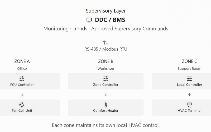
Each controller remains connected directly to its own HVAC terminal. Modbus is the information and supervisory path, not the electrical power or safety-control path.
Before commissioning, the integrator prepares a point list for each controller family. It identifies the physical zone, controller model and firmware, Modbus slave address, baud rate, parity, register reference, data type, scaling, read/write permission and expected behavior. The list must come from the actual device documentation.
A practical point schedule should distinguish measured room temperature from setpoint, actual operating mode from requested mode, and a true equipment alarm from a communication timeout generated by the BMS. Treating these as interchangeable can produce misleading dashboards and unnecessary service visits.
Write access deserves particular attention. The BMS should only write values that are deliberately authorized; critical limits, protection functions and commissioning-only parameters should not be exposed as routine operator controls.
For the facilities team, a useful BMS view answers three questions: Which zone is outside its expected condition? What is the local controller currently asking the equipment to do? And is the information recent enough to trust? These are more useful than collecting every available register.
Central schedules may be valuable where many rooms share working hours. Yet the system must define whether a local override is permitted, how long it lasts, and which layer takes priority. Without that agreement, the BMS and room controller can repeatedly undo each other’s commands.
Safety-related functions stay with their designated equipment or safety systems. Smoke control, hazardous extraction, frost protection, airflow proving and plant interlocks must not depend on ordinary Modbus polling or a comfort thermostat.
Commissioning begins with the terminal interfaces. For each zone, verify sensor placement, fan/valve/heating outputs, equipment enable logic and local operation before connecting the network. If local control is wrong, the BMS will only make the error more visible.
Next, test the RS-485 installation: cable type and route, bus topology, address uniqueness, polarity, termination at appropriate segment ends, biasing where required and the configured serial settings. Avoid assuming that any two devices marked “Modbus” can be connected without checking their electrical and protocol requirements.
The integrator then verifies representative values end-to-end. Change a zone setpoint locally and confirm that the correct BMS point changes with the correct scaling. Test approved remote writes and local override priority. Disconnect a network segment deliberately: the BMS should mark the data unavailable, and each zone should follow its documented loss-of-communication behavior.
Finally, hand over an as-built point list, zone naming convention, communication settings, controller backups where supported and a simple fault-finding procedure. These documents matter more over the building life than an impressive commissioning-day dashboard.
The expected operational outcome is a facility where zone control remains distributed but the operating picture is centralized. Maintenance teams can identify the affected zone before visiting it, compare commanded and measured values, and distinguish local equipment issues from network faults. Integrators gain a repeatable structure for adding further compatible zones.
This approach may reduce unnecessary troubleshooting time and support better schedule discipline, but it does not establish a measured labor or energy saving. Those results require actual site data. The defensible value is clearer ownership of control, more usable operating information and a more maintainable integration.
· Local zone control continues to perform the immediate heating or cooling sequence.
· DDC/BMS provides a common view of selected conditions across otherwise separate areas.
· A documented Modbus point map makes future service and expansion less dependent on individual installers.
· Explicit command priority prevents central schedules from silently conflicting with local overrides.
· Commissioned communication-failure behavior separates loss of visibility from loss of HVAC operation.
· Terminal-specific controller selection avoids forcing unlike equipment into one wiring arrangement.
The approach is suitable for industrial sites with multiple comfort-conditioning zones and compatible controllers that expose the required Modbus points. It is particularly relevant when an existing DDC/BMS needs better room-level visibility without replacing functional local control equipment.
It is not a substitute for industrial process automation, life-safety systems or a fully engineered plant-control sequence. Nor should a product be described as BACnet-, KNX- or Modbus-capable without checking the exact model and interface. For mixed-protocol sites, a properly specified gateway or DDC interface may be necessary.
CosyClimate offers HVAC room-control solutions for compatible fan-coil, heating and mixed terminal applications, including selected Modbus-enabled controllers.
Contact CosyClimate to share the equipment schedule, wiring diagrams, required points, network topology and intended BMS functions. We assess the local controller configuration for a workable integration.
Email:info@cosyclimate.com
Phone:+86 13520339098
Add:Tongzhou District, Beijing, 101199 China