Welcome to CosyClimate
Navigation
Position:Home > News > Blog
Blog
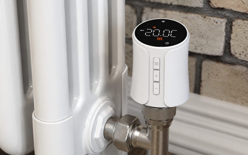
[October, 2026]A heating upgrade should not begin with a wall chase. In many occupied homes, the better first question is which part of the existing system can be controlled more intelligently without disturbing the building fabric.Who This Article Is ForFor European heating installers, retrofit contractors, HVAC distributors, renovation specialists and property managers working in occupied houses and apartments where new control cables are costly, disruptive or prohibited.Quick AnswerThere are several credible ways to improve heating control without running new cables through finished rooms: replace manual radiator heads with smart TRVs; reuse an existing two-wire boiler thermostat connection where the electrical interface allows; use an RF room thermostat and receiver; retrofit wireless room control to an existing underfloor-heating manifold; or use a suitable plug-in thermostat for a compatible electric heater. Each solves a different wiring problem. None is universally suitable, and “wireless” never means that every part of the system is wire-free.Why “No Rewiring” Needs a Precise DefinitionA homeowner may mean no wall chasing, no new cable between rooms, or no electrical work at all. Those are three different constraints. An RF thermostat avoids a new cable between the room and receiver, but the receiver still needs a correct connection at the boiler. A smart TRV avoids thermostat wiring at the radiator, but cannot create boiler demand by itself unless the chosen ecosystem supports that coordination. A wireless UFH thermostat can avoid a new room-to-manifold cable, yet a wiring centre and actuators still require power and local wiring.Before specifying equipment, establish exactly what existing wires, valve bodies ,manifolds and heat-source interfaces are available. A short site survey is usually cheaper than a return visit with the wrong product.Five Practical Options at a GlanceRetrofit optionBest-fit existing systemWhat stays wiredMain limitation1. Smart TRVsWater radiators with compatible thermostatic valve bodiesBoiler/pump and heating distributionRoom demand may not reach the boiler2. Two-wire boiler thermostatExisting room-thermostat cable and compatible boiler inputExisting two-core runTwo wires do not identify voltage or protocol3. RF thermostat + receiverBoiler control where a new room cable is undesirableReceiver at heat sourceRF range and receiver wiring must be verified4. Wireless UFH zoningExisting hydronic manifold with accessible wiring centreManifold actuators and centreActuator and zone mapping still need work5. Plug-in electric controlSuitable plug-connected electric heaterHeater plugs into controlled outletElectrical rating and heater restart behaviorOption 1 — Smart Radiator Valves: Upgrade the Room, Keep the PipesWhere a home already has water radiators with compatible thermostatic valve bodies, smart thermostatic radiator valves (TRVs) are often the least disruptive entry point. The installer replaces the existing thermostatic head, checks the valve pin and fits the correct connector or adapter. The pipework and radiator remain in place.The real value is room-by-room scheduling. A bedroom can have a different heating period from the living room, and a rarely used guest room need not follow the main occupied zone. This is especially useful in European radiator retrofits where rooms already have local valves but no independent digital control.The hidden issue is heat-source demand. A TRV opening in a cold bedroom does not guarantee that the boiler will fire. If the boiler is governed by a central thermostat in a warm living room, the bedroom may still receive no heat. For larger retrofits, review whether the existing thermostat remains the demand authority or whether a compatible demand controller and receiver are required.Also inspect the mechanical system: a sticking valve pin, poorly balanced circuit, air in the radiator or a covered TRV can defeat an otherwise well-configured smart system. WiFi and Zigbee change communications, not hydraulics.Option 2 — Reuse the Existing Two-Wire Boiler Thermostat CableA common renovation constraint is a finished wall with only two conductors at the old thermostat location. Keeping those conductors may be possible, but the phrase “two-wire thermostat” is not an electrical specification.The two wires might be a volt-free contact circuit, a switched-live control, a low-voltage connection, a manufacturer-specific communications bus or another arrangement. The installer must identify the boiler terminals, the expected signal and whether the new thermostat needs a separate supply. Never assume a 230 V thermostat can be fitted just because two conductors are present.When the existing cable and boiler interface are suitable, a dedicated two-wire retrofit solution can preserve the room location without cutting new channels. Where the old wiring cannot power the desired thermostat, a battery-powered room unit or RF solution may be the better route.The decisive test is compatibility with the actual boiler and its control mode. Replacing a modulating or proprietary controller with a basic on/off contact may sacrifice functions even if it switches the boiler successfully.Option 3 — RF Room Thermostat and Boiler ReceiverAn RF thermostat separates the user interface from the heat-source connection. The room unit can often be battery powered and placed in a sensible occupied location, while a receiver is installed near the boiler and connected according to the boiler manufacturer’s instructions.This is useful when the old thermostat is badly located, the existing cable is damaged or the customer wants a different room-control position without opening walls. The receiver does not eliminate electrical work at the boiler; it relocates it to an accessible point.RF range should be tested in the real building, not inferred from an open-air headline. Thick masonry, reinforced concrete, service cupboards and the boiler’s location can affect communication. Also check pairing, loss-of-signal behavior, battery warnings and the procedure for replacing either device.RF is not synonymous with WiFi. Some RF systems work as a local thermostat-receiver pair without internet access. Whether remote app access exists is a separate product capability.Option 4 — Wireless Room Control for an Existing UFH ManifoldHydronic underfloor heating presents a different retrofit problem. The manifold and thermal actuators may be perfectly serviceable, but running new thermostat cables to every finished room is undesirable. Wireless room thermostats can send demands to a compatible RF wiring centre located near the manifold.This can retain the floor circuits and much of the hydraulic installation. However, the wiring centre still needs correct power, actuator connections and, where applicable, pump or heat-source coordination. “Wireless UFH” describes the room communication path, not the entire system.Map every room to its manifold loop or loops before connecting the controller. One room may have multiple loops; one manifold can serve rooms on different floors. A control zone is not necessarily one actuator. Confirm actuator voltage, normally closed/open type, circuit capacity and the compatibility of the chosen RF components.Commission each room separately: create a demand, observe the relevant actuator response, and verify that no adjacent zone has been assigned incorrectly. Because thermal actuators move slowly, allow sufficient time before declaring a circuit faulty.Option 5 — Plug-In Control for Suitable Electric HeatingFor a portable or plug-connected electric heater, a correctly rated plug-in thermostat or smart controlled outlet may provide scheduling or temperature control without fixed rewiring. This is not a general solution for hardwired electric floor heating, electric boilers or high-load appliances.Check the heater’s rated current, starting behavior, grounding requirements and manufacturer instructions. Some heaters do not resume heating automatically when power is restored, making external switching unsuitable. Never exceed the controller’s rated load or use an adapter arrangement that compromises electrical protection.A plug-in control may be convenient in a single room. It should not be presented as a replacement for a properly engineered whole-home heating system.How to Choose: Follow the Existing Heat DistributionStart with what physically delivers heat. Radiators point toward valve-based room control; a boiler with a usable thermostat connection points toward two-wire or RF room control; an existing UFH manifold points toward wireless zoning; a suitable portable electric heater may allow plug-in control. Then decide whether the goal is one improved room or coordinated heating throughout the property.Site findingFirst option to evaluateQuestion that changes the answerRadiators with manual thermostatic headsSmart TRVsDoes the boiler receive heat demand from rooms?Old boiler thermostat on two conductorsReuse two-wire routeWhat exactly is on those terminals?Boiler thermostat needs a new room locationRF thermostat + receiverCan the receiver be wired and RF signal proven?UFH manifold present, no usable room cablesWireless UFH zoningAre actuators and wiring centre compatible?Portable plug-in electric heaterRated plug-in thermostatWill the heater restart safely after switching?Three Retrofit Mistakes That Create Expensive CallbacksMistake one: choosing the wireless protocol before checking the heating interface. A WiFi app does not establish whether a thermostat can switch the correct boiler input, and a Zigbee gateway does not solve a stuck radiator valve.Mistake two: assuming a room controller is the entire system. Multi-room radiator control may need boiler demand coordination; UFH may need a wiring centre, thermal actuators and a heat-source signal. The device visible on the wall is only one part of the control chain.Mistake three: skipping the occupied-home handover. Customers need to know how to change the setpoint locally, what happens without internet, who owns the app account, how batteries are replaced and whom to call after a router or receiver change.A Realistic Example: A Finished Three-Bedroom HomeConsider an older home with radiators, a central boiler thermostat in the living room and no appetite for opening decorated walls. The bedrooms are often colder than the living room. Smart TRVs can give the bedrooms individual schedules, but the boiler may still stop when the living-room thermostat is satisfied. The right solution is not simply to add more valves; it is to decide how room requests will interact with boiler demand. That might mean retaining the existing thermostat with understood limitations, or selecting a compatible coordinated control arrangement. The site survey determines the choice.This is an illustrative selection scenario, not a claimed CosyClimate installation.Pre-Order and Commissioning Checklist· Record heat source make/model and its required control interface.· Photograph existing thermostat terminals and identify voltage/signal safely.· Identify radiator valve bodies, adapter needs and free pin movement.· Count rooms, radiators, UFH loops and actual control zones separately.· Confirm who currently starts and stops the boiler or pump.· Check RF/WiFi/Zigbee coverage in actual device locations.· Confirm receiver, gateway, wiring-centre and actuator compatibility.· Verify thermostat and receiver power requirements.· For electric heaters, confirm load rating and safe restart behavior.· Document expected operation during internet or radio loss.· Test one representative zone before scaling the installation.· Handover schedules, account ownership, battery instructions and wiring records.Conclusion: Less Disruption Requires Better DiagnosisAvoiding new wall wiring is a sensible renovation objective, but it is not a product category on its own. The practical choice depends on the existing heating hardware, control signals, available power and the level of coordination the customer expects. Smart TRVs, two-wire boiler retrofits, RF room control, wireless UFH zoning and plug-in electric control can all be valuable—when each is used for the problem it actually solves.For contractors, the best retrofit is not the one with the fewest visible wires. It is the one that can be installed, commissioned and maintained without surprises. Discuss a Low-Disruption Heating Retrofit with CosyClimateCosyClimate supplies heating-control options for radiator, boiler and underfloor-heating applications, including smart TRVs, wireless controls, selected two-wire retrofit solutions, wiring centres and compatible accessories. The correct configuration depends on the heat source and installation.For distributors, installers and project contractors, share the existing heating type, available wiring, room count, valve or manifold details and intended control functions. We can help identify which control architecture is worth evaluating before you commit to the full retrofit.Contact CosyClimate  to discuss your next HVAC control project.
[October, 2026]An FCU project may start with three-speed AC fans and finish with a mix of AC and EC units. The room-control strategy should not become a last-minute redesign because the fan motor changed.Who This Article Is ForFor European HVAC contractors, MEP designers, FCU manufacturers, system integrators, wholesalers and project buyers specifying new buildings, phased upgrades or mixed fan coil portfolios.Quick AnswerTraditional AC fan coils commonly use separate low, medium and high speed outputs. EC fan coils commonly accept a low-voltage 0–10 V speed reference, but their enable and power requirements vary. A flexible room-controller platform can support either architecture, provided the selected hardware has the correct outputs and the FCU electrical interface is verified. A 0–10 V output is not a substitute for three mains-voltage speed relays, and the two must never be wired interchangeably.1. Why AC-to-EC Transitions Complicate a Simple Thermostat OrderOn a specification sheet, “fan coil thermostat” can look like a single item. On site, an AC fan terminal block and an EC fan input are different electrical interfaces. A contractor may discover that the room controllers were purchased against an early FCU schedule, while the equipment supplier later proposed EC fan motors for selected rooms. The wall plate may still fit. The wiring and commissioning assumptions may not.This is most visible in phased renovations: one floor retains existing three-speed FCUs while another receives new EC units. Standardizing the user experience is useful, but standardizing the wrong output hardware creates change orders.2. What Three-Speed AC Fan Control Actually MeansA conventional three-speed AC fan coil commonly exposes separate terminals for low, medium and high speed. The thermostat selects one speed using appropriately rated switched outputs; the exact circuit must follow the FCU manufacturer’s diagram. Simultaneously energizing multiple speed taps can damage equipment, so relay interlocking and correct wiring are essential.The three settings are discrete. “Medium” is not a universally defined airflow or electrical consumption: it depends on the fan and coil model. Even two FCUs with the same thermostat can deliver different noise and airflow at the same selected speed.3. What Changes with EC Fan ControlAn electronically commutated (EC) fan often accepts a proportional control reference such as 0–10 V DC. The controller requests a fan speed through an analog signal instead of selecting one of three AC speed taps. However, the fan may also need a separate enable input, permanent power, a minimum-start threshold or a manufacturer-specific configuration.Do not assume that 0 V always means fan off or that 10 V always means the same maximum airflow. Some drives define a minimum operating voltage, a non-linear response, an inverted option or a separate run/stop contact. The FCU technical manual, not the thermostat brochure, establishes the correct sequence.4. AC and EC Control: What the Contractor Must CompareDesign questionAC three-speed FCUEC 0–10 V FCUFan speed commandSeparate switched low / medium / high outputsAnalog 0–10 V reference; enable may be separateElectrical interfaceCheck voltage, relay rating and speed-tap interlockCheck input impedance, reference ground, polarity and signal rangeSpeed behaviourThree fixed choicesPotentially variable speed, subject to drive mappingFan-off commandAll speed outputs off, subject to equipment designMay require 0 V and/or dedicated enable-offCommissioning checkEach speed individually; no simultaneous outputsMeasure signal and verify fan response at several setpointsControls riskIncorrect mains switching or crossed speed wiresIncorrect common/reference or wrong enable sequence5. The Universal Controller Question Is More Specific Than It SoundsA genuinely flexible FCU controller is not one that can be made to look compatible in a catalogue. It must provide the physical output types needed by the actual fan: switched speed relays for AC and a suitable analog reference for EC. The installer must then select the correct operating mode and terminate wiring to the matching terminals.CosyClimate’s universal FCU control range includes configurations designed for AC three-speed or EC 0–10 V fan applications. That capability should be checked against the exact model and wiring diagram, not inferred from a family name. “Universal” also does not imply that every controller can operate both fan types at once.6. Fan Type Is Only Half the I/O ScheduleAn FCU thermostat also has to control water valves, heating/cooling modes and sometimes auxiliary equipment. A two-pipe FCU with one changeover valve is different from a four-pipe FCU with separate heating and cooling valves. Valve actuators may be on/off or proportional. Their supply voltage and control signal cannot be guessed from the fan type.A controller with 0–10 V fan output may still have on/off valve relays; that can be entirely appropriate if the selected valve actuators are on/off. Conversely, an EC fan does not automatically mean a proportional valve is installed. Specify each output independently.7. An Example of the Wrong AssumptionConsider an office retrofit where the mechanical schedule lists EC fan coils but the electrical subcontractor receives a thermostat schedule copied from an older AC project. The controller arrives with three switched speed terminals and no analog fan output. It can mount on the wall and display a fan icon, but it cannot generate the signal required by the new EC drive.The correction may involve replacing the controller, revising the room wiring, updating the BMS point list and retesting the sequence. The preventable mistake occurred before procurement: nobody reconciled the FCU terminal schedule with the controller I/O schedule.8. A Flexible Platform Helps When the Building Has Mixed EquipmentMixed FCU stock is common during phased refurbishment, tenant fit-outs and projects using more than one FCU supplier. The practical goal is to keep a consistent room interface, commissioning approach and support documentation while allowing different fan-output configurations behind the wall.That does not remove the need to track room-by-room settings. The commissioning record should identify which room uses AC or EC mode, valve arrangement, sensor source, heating/cooling logic and communication address.9. What 0–10 V Can Improve—and What It Cannot PromiseProportional fan control can offer finer adjustment than three discrete speed steps. At appropriate operating points it may help reduce noticeable speed changes and allow the system designer to balance airflow and acoustic comfort more precisely. Whether it reduces noise or energy in a given project depends on the EC fan, coil selection, control curve, operating hours and hydronic design.Do not publish blanket percentage savings without measured project data. An incorrectly configured minimum speed can cause poor air distribution, while a continuously running fan can undermine expected energy performance. Better controllability creates an opportunity; it is not an automatic outcome.10. Commission the Fan Sequence, Not Just the DisplayA thermostat showing 40% fan speed does not prove that the fan is running at 40% of rated airflow. The percentage may only represent an output reference. Commissioning should verify actual fan response and acceptable noise at several commands, including minimum, mid-range and maximum.For EC units, measure the voltage at the fan input under load and confirm the correct common/reference. For AC units, verify each selected speed and that other speed outputs remain off. Test fan stop, power recovery, heating/cooling transition and any occupancy or window-contact logic required by the project.11. Minimum Speed and Fan-Stop Logic Deserve Their Own LineSome EC fans will not rotate reliably below a defined reference. Others continue running at a minimum speed unless an enable contact is opened. A room controller should not assume that “set output to zero” always means “fan off.”Where a valve closes before the fan stops, or where post-purge is required, the sequence needs explicit agreement. Fan delays and anti-draft settings should be aligned with the equipment and application, rather than copied blindly between AC and EC projects.12. BMS Integration Does Not Replace Correct Local WiringModbus or another building-control connection can make setpoints, modes and status visible centrally. It does not convert an AC speed relay into an EC analog output. The room controller must first control the physical equipment correctly.Before BMS commissioning, confirm RS485 addressing, baud rate, register mapping, writable points, priority rules and what happens when communication fails. The BMS should not inadvertently command fan operation against local protection or the approved room sequence.13. What to Freeze Before the Purchase Order· FCU make/model and terminal diagram for every equipment variant· AC three-speed or EC proportional fan input; exact voltage and reference requirements· Whether EC fan needs separate run/stop or minimum-speed settings· Two-pipe/four-pipe arrangement and valve output type, voltage and quantity· Room sensor, return-air sensor and any external sensor requirement· Occupancy, key-card, window contact or condensate interlock requirements· Standalone versus BMS operation, communication type and point list· Approved controller model, wiring drawing, mounting format and configuration revision14. A Small Mock-Up Can Prevent a Large Site ProblemBefore releasing hundreds of controllers, build one representative room or bench setup for each distinct FCU electrical configuration. Use the actual controller, actuator and fan interface—or a supplier-approved simulator where full equipment is unavailable.Test speed control, heating and cooling outputs, sensor behaviour, fan stop, restart and BMS communications. Record the final settings and label the approved configuration. The objective is not an impressive demonstration; it is to expose mismatched assumptions while changes are still cheap.15. A Practical Selection MatrixProject conditionPreferred controller capabilityVerify before approvalExisting AC three-speed FCUsCorrectly rated three-speed switched fan outputsFan voltage, wiring taps and interlockingNew EC 0–10 V FCUs0–10 V analog fan reference; enable if neededInput range, common, start threshold and fan-off logicMixed AC/EC buildingController platform with separate supported AC and EC configurationsRoom-by-room mode schedule and wiring detailsBMS-connected projectLocal fan/valve I/O plus required integration interfaceRegister list, addressing and offline operation16. What Distributors and OEMs Gain from One Control FamilyA distributor serving several FCU brands can reduce sales confusion by organizing its range around application compatibility rather than selling an unrelated thermostat for every fan motor. A shared appearance and menu structure can also simplify installer training and spare-parts support.But the SKU logic must remain honest. If AC and EC functions require different hardware variants, label them clearly. Keep approved wiring diagrams close to the model codes, and do not market software configuration as a substitute for missing terminals.17. The Better Question for Every FCU ProjectInstead of asking, “Does this thermostat support fan coils?”, ask: “Which exact fan command, valve command and system sequence does this FCU require?” The answer is concrete enough to verify before ordering and test after installation.Moving from AC to EC fan coils is an opportunity to improve control flexibility. It should not create uncertainty about electrical compatibility. The strongest strategy is a consistent controller platform with precisely matched outputs, documented configuration and repeatable commissioning. Discuss Your AC / EC Fan Coil Control Requirements with CosyClimateCosyClimate provides FCU thermostat solutions for AC three-speed and EC 0–10 V fan applications, including selected models with Modbus and WiFi options. For an accurate recommendation, share the FCU electrical diagram, fan interface, valve type, pipe arrangement and BMS requirements. We can help match the controller configuration to the equipment before your project order is finalized.Contact CosyClimate  to discuss your next HVAC control project.
[October, 2026]A thermostat can match the tender description and still be wrong for the equipment delivered to site. The expensive part is rarely the thermostat itself.Who This Article Is ForFor HVAC and MEP contractors, site engineers, purchasing teams, commissioning engineers and system integrators responsible for selecting room controls before installation. The aim is to prevent avoidable changes between approved submittal, purchase order and commissioning.Quick AnswerBefore ordering thermostats, confirm the installed equipment interface, not just the room schedule: fan type, valve control signal, supply voltage, heating/cooling sequence, actuator or boiler demand circuit, wall-box and wiring conditions, sensor location, and any BMS read/write requirements. Record unresolved items as hold points. Test a representative room before releasing the full quantity when project variations or interface risks remain.1. The Change Order Usually Starts Before the Purchase OrderA common sequence is familiar. The controls schedule says “FCU thermostat, 2-pipe, BMS ready.” Purchasing obtains a compliant-looking quotation. When installation starts, the fan is EC rather than three-speed AC, the valve actuator needs a different signal, or the electrical box is too shallow. The device may not be defective. The selection process was incomplete.The commercial consequence is larger than the replacement unit price: another approval round, delayed commissioning, electricians returning to completed rooms, re-labeling, transport, and sometimes a claim over whose specification was wrong.2. Use the Actual Equipment Schedule, Not Only the Room Name“Hotel bedroom,” “office meeting room” and “apartment living room” describe spaces, not electrical control interfaces. Even rooms on the same floor can contain different FCU generations or valve arrangements after phased refurbishment.For each control type, link the thermostat schedule to the current mechanical equipment schedule and the electrical schematic. If a drawing revision changes the FCU or actuator, it should trigger a control compatibility review rather than silently carrying forward the old thermostat model.3. AC and EC Fan Outputs Are Not InterchangeableA three-speed AC fan commonly needs switched outputs for low, medium and high speed. An EC fan may need a 0–10 V speed command, sometimes alongside a separate enable signal. Both may be described as “three-speed fan coil” in an early schedule, but they are not wired or controlled the same way.Confirm the fan motor type, supply, speed interface, enable requirement and the behavior expected at minimum speed. For a retrofit, inspect the actual fan terminal diagram. Do not infer an EC interface from a product brochure that merely says “variable speed.”4. Valve Type and Control Signal Must Be Written DownA 230 V On/Off valve actuator and a modulating 0–10 V actuator may both be mounted on a similar FCU. The thermostat output has to match the actuator input. Check whether heating and cooling use separate actuators, one changeover valve, or a shared arrangement.A controller advertising both relay and 0–10 V capability is not proof that every combination can operate simultaneously. Review output allocation, common terminals, power limits and the exact sequence supported by the selected model.5. Two-Pipe and Four-Pipe Are Control Sequences, Not Marketing LabelsFor two-pipe FCUs, establish how the system changes between heating and cooling: seasonal central changeover, water sensor, BMS command or local selection. For four-pipe systems, confirm separate heating and cooling outputs and whether simultaneous demand is prevented.A “2/4-pipe selectable” thermostat still needs the correct wiring, valve outputs and changeover logic. Agree who supplies the changeover signal and what happens if it is absent.6. UFH: Count Zones and Identify the ActuatorsIn hydronic underfloor heating, one room may have two manifold loops but only one temperature zone. The thermostat can control an actuator directly or send a demand signal through a wiring center. These are different wiring and loading arrangements.Record actuator voltage, normally closed/open type, total connected load, wiring-center input requirements, zone count and whether pump/boiler demand is produced centrally. A photograph of the manifold and actuator label often resolves more than another round of catalogue comparison.7. Electric Heating Requires a Load CalculationElectric floor-heating thermostats may directly switch heating cable or mat loads. Check connected wattage, supply, relay rating, protective arrangements and whether an external contactor is required. Confirm floor-sensor type and installation position where floor-temperature limiting is part of the design.Never substitute a low-load water-heating thermostat merely because its faceplate and menu look identical.8. Boiler “Dry Contact” Must Not Be Confused with PowerA volt-free relay contact is an isolated switching function; it is not a power supply for the wall thermostat. Old boiler installations may provide only two control conductors and no neutral. Some boilers use switched voltage or proprietary/modulating communication instead of a simple demand contact.Check the boiler terminal diagram and available room wiring before selecting battery, mains or RF receiver architecture. Do not bypass manufacturer-required safety or control interlocks to make a generic thermostat fit.9. Wall Boxes, Cable Cores and Sensor Positions Are Site ConditionsA flush thermostat may require a particular back-box depth, mounting standard and cable arrangement. On refurbishment projects, the existing box may be shallow, off-center or missing the permanent supply required by a connected model.Also inspect the sensing location. A thermostat placed beside a doorway, behind a curtain or in direct sun may produce complaints even when the electrical installation passes. Sometimes a surface-mounted or RF room unit is the less disruptive and more accurate choice.10. BMS Ready Is Not a Complete Integration SpecificationFor Modbus RTU, obtain the register map before purchase approval. Confirm which points can be read and written, data types, scaling, setpoint limits, addressing, baud rate, RS485 wiring and local-versus-central command priority.Ask a practical question: if the BMS writes a setpoint while a guest changes it locally, which value wins and for how long? If nobody can answer, the integration design is not finished.11. The Submittal Should Record Assumptions and ExceptionsA supplier may quote against incomplete information. The contractor should not convert those assumptions into an unconditional purchase order without review.Mark every uncertain interface as confirmed, assumed or open. Attach the equipment schedule revision, wiring diagram and relevant supplier clarifications. If the valve signal or fan motor is still unknown, keep that line on technical hold instead of letting the warehouse quantity create false confidence.12. Define What Is Included in “Thermostat Supply”A room-control package may require external sensors, gateways, RF receivers, actuator adapters, mounting plates or power supplies. If these are missing from the bill of materials, installation can stop even though all thermostats arrived.Separate included accessories from project-supplied items. For large buildings, also identify spare units, labels, configuration tools and who performs pairing or address setup.13. Sample Room First; Bulk Release SecondA representative room should demonstrate the full chain: sensor reading, heating/cooling request, fan operation, valve response, schedule, card/window input where used, power recovery and BMS behavior. A sample test should use the actual actuator and FCU or an electrically equivalent bench setup.If the building has several equipment variants, one room is not enough. Test one of each meaningful control type. Sign off the parameter set and wiring detail before the same error is repeated across 200 rooms.14. Who Owns a Change When Equipment Is Substituted?A late FCU substitution can change the thermostat requirement even when the room function stays the same. The project needs a defined review trigger: changes to motor, valve actuator, voltage, control interface or plant sequence must be checked against the approved controls submittal.This is less about allocating blame than preventing a small mechanical change from becoming a site-wide controls rework.15. A Contractor’s Pre-Order Decision TableItemEvidence to ObtainRelease RiskFCU fanMotor/terminal diagram: AC switched speeds or EC 0–10 VWrong fan outputsFCU valvesActuator label, voltage, On/Off or modulating signalWrong valve interfaceHeating/cooling2/4-pipe sequence and changeover sourceIncorrect operationUFH zonesManifold/actuator schedule, wiring-center inputsWrong zone/load countElectric heatingInstalled load, floor sensor, protection designUnderrated switchingBoilerControl terminals, room wiring, power sourceUnsafe/incompatible demandMountingBack-box, cable cores, sensor locationRework to finished wallsBMSRegister list, authority and RS485 designCommissioning delayAccessoriesReceiver/gateway/sensors/adapters listIncomplete delivery16. Questions to Close Before Purchase Approval· Has the final equipment schedule been reconciled with the thermostat schedule?· Are fan, valve and actuator electrical interfaces confirmed by current drawings or labels?· Is the heating/cooling sequence and changeover source agreed?· Are thermostat power, cable cores and wall-box dimensions verified?· Are external sensors and mounting accessories included?· Are boiler contacts and any proprietary interfaces documented?· Is the BMS point list and command priority approved?· Have the contractor, supplier and integrator agreed configuration responsibility?· Are equipment substitutions subject to controls review?· Has each representative control variant been tested?· Are open assumptions clearly marked as purchase hold points?· Are spares, labels and commissioning records included in handover planning?17. A Better Purchase Order Is the Result of a Better Technical HandoverContractors do not need the most elaborate thermostat for every room. They need a controller whose electrical outputs, configuration and integration behavior match the equipment actually installed.A short technical hold before ordering can be cheaper than one return visit after ceilings and walls are finished. The most useful supplier is not the one who says yes to every schedule line; it is the one who identifies the missing information while there is still time to correct it. Talk to CosyClimate About Project Thermostat SelectionCosyClimate supports HVAC contractors, distributors and integrators with thermostat solutions for FCU, UFH, boiler and connected room-control applications. Depending on model, options include AC/EC fan interfaces, On/Off or 0–10 V valve control, external sensing, Modbus and WiFi.Send the equipment schedule, wiring diagram, required I/O, project quantity and any BMS point requirements. We can help clarify product compatibility and configuration before the purchase order is finalized.Contact CosyClimate  to discuss your next HVAC control project.
[October, 2026]For one radiator, the protocol may feel like a product feature. For ten or twenty radiators, it becomes part of the heating-system architecture.Who This Article Is ForThis article is for heating installers, smart-home integrators, HVAC distributors, retrofit specialists and product managers selecting connected radiator controls for European homes, apartments and multi-room heating projects.Quick AnswerWiFi and Zigbee can both work well for smart radiator control, but they solve connectivity differently. WiFi can be practical when a small number of radiator thermostats need direct access through the home's existing network. Zigbee becomes more attractive when several heating devices need to operate as one local ecosystem through a gateway.Do not choose only by protocol name. Device count, building layout, gateway strategy, router ownership, commissioning, maintenance and boiler coordination matter more. Neither protocol fixes a sticking valve pin, poor radiator balance or an unsuitable valve body.1. Start with the Heating Problem, Not the RadioA smart radiator thermostat has a mechanical job before it has a wireless job: it has to move the radiator valve correctly and regulate the room. Check the valve body, adapter, valve-pin movement and thermostat position first. A connected head fitted to a seized valve is still a seized valve. Once the radiator side is sound, connectivity becomes meaningful.2. WiFi: Fewer System Components, More Dependence on the Home NetworkDirect WiFi is easy to understand. The device joins the local wireless network and, depending on the platform, connects to an app or cloud service without a separate Zigbee gateway. That can suit one room or a few radiators. The trade-off is that router replacement, SSID/password changes, 2.4 GHz coverage, account ownership and internet troubleshooting become part of support. With two devices this may be trivial. With twenty, it deserves more thought.3. Zigbee: Add a Gateway, Simplify the Endpoint NetworkA Zigbee radiator thermostat normally communicates with a compatible gateway. In a multi-device heating system, this creates a defined local network instead of asking every endpoint to join the resident's WiFi. The gateway is a real system component: it needs power, a sensible location, backhaul and a clear replacement and pairing procedure. Zigbee should be evaluated as an architecture, not as a logo on the box.4. One Radiator and Fifteen Radiators Are Different DecisionsFor one or two radiators, direct WiFi may keep the installation simple. As the number of rooms grows, a gateway-based Zigbee architecture can make device grouping and network management more structured. Scale changes the decision because commissioning, naming, battery maintenance and recovery all multiply with the device count.5. Do Not Oversell Zigbee MeshZigbee is often described simply as a mesh network. Actual routing depends on device type and product architecture; battery endpoints commonly prioritize low power and may not act as routers. Gateway position, building construction and any mains-powered routing devices still matter. Test the real network rather than assuming the word mesh guarantees coverage.6. WiFi Coverage Is Also a Building QuestionA phone working well in the living room does not prove reliable coverage at every radiator. Radiators often sit under windows, near external walls and behind furniture. Before a larger WiFi TRV installation, check coverage where the devices will actually be installed.7. Battery Life Is More Than a Protocol ClaimReal battery life depends on valve movement, communication frequency, signal conditions, motor load, temperature, firmware and usage. Avoid promising a fixed service interval based only on WiFi or Zigbee. In a multi-device home, low-battery reporting and simple replacement matter as much as the headline figure.8. The App Experience MattersFor residential customers, the protocol becomes invisible after installation. What they experience is room naming, grouping, schedules, shared access and recovery after a phone or router change. Distributors should evaluate the complete user journey, not only the valve head.9. Gateway Capacity Is a Real SpecificationFor Zigbee, ask how many heating devices the gateway is designed to support and whether it supports only TRVs or a broader heating ecosystem. A small apartment may never reach the limit; a villa with thermostats and many radiator valves might. Capacity planning is easier before installation than after the last room refuses to pair.10. Room Grouping Is Not the Same as Device GroupingTwo radiators in one living room usually belong to one comfort zone even though they are separate wireless devices. Plan room zones first and device names second. Heating logic should reflect how people use the space, not how many valves are installed.11. Boiler Coordination Is Where Multi-Room Control Becomes a Heating SystemA radiator valve can stop flow through one emitter. It does not automatically tell the boiler whether the home still needs heat. An existing central thermostat may remain responsible for boiler demand, or a compatible receiver/controller may coordinate several rooms. If all smart TRVs are satisfied while an unrelated thermostat still calls for heat, the wireless protocol was not the main design problem.12. The Existing Wall Thermostat Can Become the LimitationA bedroom can ask for heat while the central thermostat sits in a warm living room and has already stopped the boiler. The bedroom TRV may be fully open but no useful heat arrives. Decide deliberately whether the existing central thermostat remains the heat-source authority after room-by-room zoning is introduced.13. What Should Work When the Internet Is Down?Confirm whether local setpoint changes and schedules continue when cloud access is unavailable. In a Zigbee system, understand what remains available when the gateway has power but loses internet access. Offline behavior varies by platform and should be tested rather than assumed.14. Router and Gateway Replacement Are Lifecycle QuestionsWiFi devices may need reconnection after credentials change. A Zigbee system may require gateway migration or re-pairing depending on the platform. For two devices this is inconvenience; for twenty it is a maintenance procedure. Leave enough information for someone other than the original installer to recover the system.15. Rental Properties Change the DecisionIn an owner-occupied home the resident usually controls the router and app account. In rental property, those responsibilities change with tenants. Direct WiFi may require more network handover; a gateway architecture may centralize device management, but account ownership and backhaul still need definition. There is no automatic winner.16. WiFi and Zigbee Do Not Fix Hydronic ProblemsIf a radiator never heats properly, check valve movement, air, sludge, balancing and flow before blaming the network. A useful diagnostic sequence is: is the thermostat commanding, is the valve moving, and is hot water actually reaching the radiator?17. Open-Window Detection Is Independent of the RadioOpen-window detection is usually based on local temperature behavior. It can reduce unnecessary heating when a rapid temperature drop is detected, but it is not the same as a dedicated window contact. Evaluate the control function separately from the wireless protocol.18. For Distributors, Stock the Architecture Your Customers Actually BuyA distributor does not necessarily need equal stock of WiFi and Zigbee TRVs. Direct WiFi may fit installers upgrading a few radiators; Zigbee may deserve stronger emphasis where customers build whole-home systems. Stock depth should follow channel, project size and support capability.19. Practical Selection Checklist· How many radiators will be controlled now and later?· How many actual room zones do they represent?· Are valve bodies compatible and valve pins free?· Will curtains or covers distort temperature sensing?· Who owns and maintains the home network?· Is direct WiFi desirable or is a gateway acceptable?· If Zigbee is used, where will the gateway be installed?· What device capacity does the gateway/platform support?· Has coverage been checked at actual radiator positions?· How are multiple radiators in one room grouped?· How is boiler demand generated?· Will the existing central thermostat remain?· What continues during internet loss?· What is the recovery process after router/gateway replacement?· How are low batteries reported?· Who owns the app account after handover?· Has a representative room been tested before a larger rollout?20. Choose the Architecture Around the PropertyWiFi is not the simple option in every project, and Zigbee is not automatically the professional option. For a few radiators, direct WiFi can be clean and practical. As device count grows, a gateway-based Zigbee architecture may make multi-room management more structured. In either case, network ownership, coverage, recovery and boiler coordination determine whether the system remains easy to live with.The best choice is the one that still makes sense when a router is replaced, a tenant moves out or another five radiators are added. Talk to CosyClimate About WiFi and Zigbee Radiator ControlCosyClimate provides smart radiator thermostat solutions with WiFi and Zigbee options for room-by-room radiator heating control. Depending on the selected platform, solutions can include app control, scheduling, open-window detection and gateway-based multi-device management.For distributor, installer, integrator or OEM enquiries, send us the radiator and room quantity, valve types, preferred connectivity, boiler-control arrangement and target market. We can help review whether direct WiFi or a Zigbee gateway architecture better fits the application.Contact CosyClimate  to discuss your next HVAC control project.
[September, 2026]An apartment building does not become centrally managed simply because every room has a connected thermostat. The control layers have to be designed to work together.Who This Article Is ForThis guide is for MEP consultants, HVAC contractors, system integrators, developers, apartment operators, distributors and OEM product teams working on multi-apartment residential projects. It focuses on how room-level heating control, apartment-level zoning and building-level supervision can be combined without making the system unnecessarily complex.Quick AnswerA scalable apartment heating-control system usually works in layers. Room thermostats regulate local comfort. Apartment-level wiring centers, actuators or zone logic coordinate heating demand inside each dwelling. The heat source or plant receives an aggregated demand appropriate to the hydraulic design. Where central supervision is required, a BMS or management platform can monitor selected room or apartment data without replacing the local control function.The right architecture depends on the heating system. Water underfloor heating, radiators, fan coils and mixed systems do not use the same field devices or demand logic. Start with the mechanical system and ownership model, then decide how much central visibility and control the building actually needs.1. One Apartment Is a Heating System. Fifty Apartments Are an Operating Model.Inside one apartment, the control problem is familiar: rooms need comfortable temperatures at different times, and the heat source needs to respond when there is demand.Across a building, another set of questions appears. Who is allowed to change what? Does the property manager need room temperatures or only apartment alarms? Are apartments individually occupied, rented or centrally operated? Is the heat source common to the building? How will maintenance identify a failed thermostat three years later?These questions are not solved by adding more smart thermostats. They are solved by defining the control layers before choosing the communication technology.2. Start with the Heating Distribution SystemThe same apartment building can use very different control architectures depending on how heat is delivered.With water underfloor heating, each room thermostat commonly controls a thermal actuator directly or through a wiring center. Several zones may share one manifold, and the wiring center can coordinate pump or boiler demand.With radiators, room-level control may be provided by thermostatic or smart radiator valves, while heat-source demand is handled separately. With fan coils, each room controller may directly operate a fan and valve. Mixed buildings can contain more than one of these approaches.The building-control design should follow these physical systems rather than trying to force them into one generic 'smart heating' diagram.3. Room Control Should Remain LocalA bedroom thermostat does not need a central server to decide that the room is cold.Local control keeps the basic heating function close to the sensor and actuator. If the internet connection, gateway or BMS is unavailable, the room should normally continue regulating according to its local settings and the agreed fallback strategy.Central management can adjust limits, schedules or operating states where the project requires it, but it should not create an unnecessary dependency for basic comfort.This separation makes the system easier to commission and more resilient after handover.4. The Apartment Is Often the Most Useful Middle LayerLarge residential projects are easier to understand when the apartment is treated as a control unit between individual rooms and the building.Within a water-UFH apartment, for example, several thermostats can call for heat through one wiring center. The wiring center operates the corresponding actuators and can provide one apartment-level heat-demand signal.That is usually more meaningful to the heat source than treating every bedroom thermostat as an independent plant command.The exact arrangement depends on the hydraulic design, but the principle is useful: aggregate demand at the level where the mechanical system is actually organized.5. Water Underfloor Heating Needs More Than Smart Wall ThermostatsA typical multi-zone UFH apartment includes room thermostats, a manifold, thermal actuators and often a wiring center.The thermostat decides whether its room needs heat. The actuator opens the relevant loop. The wiring center coordinates multiple zones and may generate pump or heat-source demand.If the project adds WiFi, Zigbee or Modbus, those communication functions sit above this physical control chain. They do not remove it.For project specification, confirm actuator voltage and type, number of zones per manifold, wiring-center capacity, heat-source demand output and how common areas or bathrooms are handled.6. Do Not Confuse Zone Quantity with Thermostat QuantityA three-bedroom apartment does not automatically require one thermostat for every heating loop.One room may contain two floor-heating loops controlled as one temperature zone. An open-plan kitchen and living room may use several loops but one room sensor. A bathroom may have its own setpoint and schedule.Count control zones according to the spaces that need independent temperature regulation, then size the actuators and wiring center around the actual manifold.This sounds basic, but it prevents unnecessary thermostats and avoids treating hydraulic loops as though they were automatically separate comfort zones.7. Central Management Needs a Clear PurposeThe phrase 'central control' can mean several different things in an apartment project.Central RequirementUseful Building-Level FunctionWhat Can Stay LocalOperator visibilityApartment/room temperatures, operating status, alarms where availableTemperature regulation and actuator controlEnergy strategySetpoint limits, occupied/unoccupied policies, common schedules where appropriateNormal room response within allowed limitsMaintenanceDevice status, fault identification, address/room mappingBasic heating operationRental / managed housingReset policies or defined landlord settingsResident day-to-day comfort adjustmentPlant coordinationAggregated demand or supervisory informationFast room-level controlIf nobody can explain what the central platform needs to do, connecting every thermostat to it may create more commissioning work than operational value.8. Modbus Makes Sense When the Building Has Someone to Integrate and Maintain ItModbus RTU can be a strong fit for professionally managed apartment buildings where room or apartment controllers need to exchange data with a BMS.The value is predictable local building integration: an integrator can map selected temperatures, setpoints, modes and statuses without depending on individual resident cloud accounts.But Modbus also brings engineering work. RS485 topology, addressing, baud rate, register mapping, command priority and commissioning records all have to be managed.For a small apartment block with no BMS and no facilities team, adding Modbus everywhere simply because the thermostat supports it may provide little practical benefit.9. WiFi Can Be Convenient, but Ask Who Owns the NetworkWiFi is attractive when residents need direct app control and each dwelling has a stable local network.The ownership question becomes important in multi-apartment projects. Is each thermostat connected to the resident's router? To a landlord-managed network? Who reconnects devices when a tenant changes the SSID or replaces the router?A system that is simple on opening day can become a support burden if network ownership changes frequently.Where WiFi is used, define account ownership, handover and offline behavior as part of the project, not after residents move in.10. Zigbee Can Reduce Direct WiFi Dependence Inside the ApartmentFor apartments with several connected heating devices, Zigbee can provide a structured local device network through a gateway.This can be useful where thermostats, smart radiator valves or other compatible heating devices need to operate as one ecosystem without every endpoint joining the resident's WiFi individually.The gateway is still a real system component. Its location, power, network backhaul, pairing procedure and replacement process matter.Do not describe Zigbee simply as 'wireless mesh' and stop there. Building construction and actual device roles still determine network performance.11. Central Control and Resident Control Need BoundariesAn apartment operator may want to limit extreme setpoints or apply a vacant-unit strategy. Residents still expect meaningful control over their own comfort.The project should define which values are local, which can be limited centrally and what happens when the two disagree.For example, the BMS might define an allowed heating range while the resident chooses the setpoint inside that range. A vacant apartment may use a background temperature until occupancy changes.These rules are easier to agree before software integration than during complaints after handover.12. Common Areas Should Not Automatically Use the Apartment StrategyCorridors, lobbies, stairwells, gyms or shared lounges have different occupancy and management requirements from private apartments.They may be centrally scheduled, use different sensors or require direct BMS supervision. Some may use fan coils while apartments use UFH.Keeping a consistent product family can still be useful, but the control sequence should follow the space.Standardization is valuable when it reduces unnecessary differences, not when it erases genuine ones.13. Mixed Heating Systems Need an Interface Between Room Demand and Heat SourceA building may combine UFH in apartments, radiators in common areas and a central boiler or heat pump plant.The plant should not receive hundreds of uncoordinated room commands. Demand is normally aggregated through the appropriate hydraulic and control layers.At apartment level this may be a wiring-center demand output. At building level it may be a zone controller, plant controller or BMS strategy depending on the system.Room thermostats should provide useful demand information, but plant sequencing belongs where the mechanical system can be understood as a whole.14. Heat Pumps Change the Importance of Control StrategyLow-temperature heating systems and heat pumps often work best with stable operation rather than aggressive room-by-room cycling.That does not make zoning unnecessary, but it means the room-control strategy should be coordinated with water temperature, system volume, minimum flow and heat-source requirements.If many small zones can close independently, the hydraulic design needs to remain safe and stable. The thermostat cannot solve minimum-flow or buffer-volume requirements.For heat-pump projects, involve the plant designer in the zoning strategy rather than treating thermostats as a separate package.15. A Hundred Apartments Need a Naming and Addressing ConventionLarge projects become difficult when device identity is improvised during commissioning.Room numbers, apartment numbers, thermostat IDs, gateway names and Modbus addresses should follow a repeatable structure. The maintenance team should be able to identify a device from the BMS and find the physical room without opening several spreadsheets.If an apartment contains six zones, record which thermostat corresponds to which manifold actuator and which configuration it uses.Good naming is inexpensive during commissioning and extremely valuable later.16. Commission One Apartment Before Commissioning the BuildingA representative apartment is the best place to test the full control chain.Check every thermostat, actuator, wiring-center output, heat-demand signal, schedule and communication function. Test power recovery and communication loss. If central management is included, verify the point list and write permissions.Then test a genuine variant - perhaps a larger apartment, a different manifold size or a mixed-emitter unit.Once the sequence is approved, freeze the configuration before repeating it across dozens of dwellings.17. Repetition Is an Advantage Only If Configuration Is ControlledApartment buildings repeat room types, but repeated hardware can still produce inconsistent operation if installer settings drift.Define approved parameter sets for each apartment or room type. Record sensor mode, output logic, schedule behavior, communication settings and any central limits.If a parameter needs to change during commissioning, update the master configuration and decide whether already completed apartments require the same revision.A building with identical thermostats but twenty different undocumented settings is not standardized.18. Maintenance Should Be Designed Before HandoverThe property team needs more than product manuals.Handover should identify thermostat models, apartment/room mapping, wiring-center types, actuator specifications, gateway locations, network addresses, BMS point lists and approved parameter sets.Also define the replacement process. If one thermostat fails, can maintenance install a spare, restore its address/configuration and return the room to service without supplier intervention?That question becomes more important as the installed base grows.19. Privacy and Account Ownership Matter in Managed Residential BuildingsConnected heating controls can cross the boundary between building equipment and resident technology.If app accounts are tied to individual residents, decide how ownership is transferred when tenants change. If a central operator can view room temperatures or occupancy-related signals, the project team should consider what data is actually necessary for operation and how access is managed.Do not collect or expose more room-level information simply because the platform makes it available.A technically connected system should still have a clear operational reason for each centrally visible point.20. Where Central Management Is Not Worth the ComplexityNot every apartment building needs a BMS connection to every thermostat.In a small owner-occupied building with independent boilers and no facilities team, local thermostats or apartment-level smart heating may provide nearly all the useful value. Central integration could add cost without creating anyone who will actually use it.Likewise, if apartments are fully independent and the building has no shared heat source, the central layer may be limited to common areas.Good system design includes knowing where to stop.21. A Practical Architecture by Project TypeProject TypeRoom LayerApartment LayerBuilding LayerSmall owner-occupied blockLocal thermostats / TRVsOptional gateway or wiring centerOften limited or noneMulti-zone UFH apartmentsRoom thermostatsWiring center + actuators + apartment demandPlant demand / optional BMSManaged rental apartmentsLocal room controlApartment zoning + defined operator limitsCentral supervision where operationally usefulLarge BMS-integrated developmentLocal thermostat controlApartment demand aggregationModbus/BMS monitoring and supervisory commandsMixed HVAC buildingControls matched to UFH/radiator/FCU zonesApartment-specific coordinationPlant/BMS integrates the building-level strategy22. Pre-Design Checklist for Apartment Heating Controls· What heating emitters are used: UFH, radiators, fan coils or a mixture?· Is the heat source individual to each apartment or central to the building?· How many genuine temperature zones are required per apartment?· For UFH, how many manifold loops and actuators are present?· What actuator voltage/type and wiring-center capacity are required?· How is apartment-level heat demand generated?· Does the heat source require minimum flow or another hydraulic constraint?· What control should remain local if the network or BMS is unavailable?· Do residents need app control? If so, who owns the account and network?· Would Zigbee gateways be apartment-specific or centrally managed?· Is Modbus/BMS integration operationally necessary?· Which room/apartment values does the central system actually need?· Which parameters can residents change and which can the operator limit?· How will device names, addresses and apartment/room mapping be structured?· Which apartment types require different parameter sets?· Has a representative apartment been fully commissioned before volume rollout?· What documentation and spare strategy will maintenance receive?· How will account/device ownership be transferred when occupancy changes?23. Design the Layers So Each One Has a Clear JobSmart heating in an apartment building is not one technology. It is a set of control layers that need to meet at sensible boundaries.The room thermostat should manage comfort. The apartment layer should coordinate zones and local demand. The building layer should supervise what genuinely needs central visibility and coordinate the shared plant where appropriate.When those roles are clear, WiFi, Zigbee and Modbus become tools rather than the architecture itself.That is what allows a project to scale from a few rooms to hundreds of apartments without turning every thermostat into a separate integration problem. Talk to CosyClimate About Multi-Zone Apartment Heating ControlCosyClimate provides heating-control solutions for water and electric underfloor heating, boiler and radiator applications, with thermostat platforms offering WiFi, Zigbee or Modbus options depending on the model. Multi-zone solutions can also include wiring centers, thermal actuators, smart radiator controls and gateway components.For apartment, residential development, distributor or OEM projects, send us the heating system, apartment/zone quantity, actuator or load requirements, heat-source demand logic and any central-management requirements. We can help review the control layers before model selection and quotation.Contact CosyClimate  to discuss your next HVAC control project.

<  12345··· >